Conversion Table
Each Syscal *.BIN file (Load Bin button) can be associated to a conversion table to assign coordinates (absolute or relative) to the electrodes to which the measurements are associated to. Without the conversion table, data will be loaded with the coordinates used for the sequence acquisition. The conversion table is a 7-column .txt file (Figure 383):
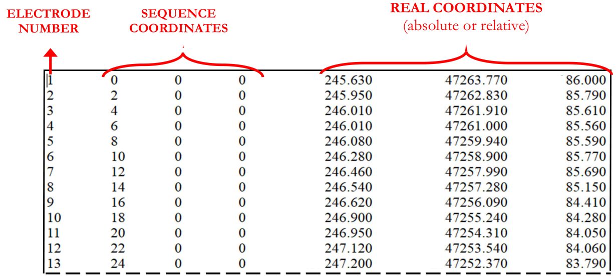
Figure 383 Example of conversion table
The conversion table can also be a 8-column file, in that case the first two columns are used to give to the electrodes a “group” and “id” identification.
Cable1   1   0   0   0   852.48   152.27   63.33
Cable1   2   1   0   0   857.94   152.20   63.03
Cable1   3   2   0   0   863.40   152.13   62.90
Cable1   4   3   0   0   868.86   152.07   63.18
Cable1   5   4   0   0   874.32   152.00   63.42
Cable1   6   5   0   0   879.78   151.93   63.06
Cable2   1   6   0   0   885.24   151.87   63.27
Cable2   2   7   0   0   890.70   151.80   62.89
Cable2   3   8   0   0   896.16   151.73   62.53
Cable2   4   9   0   0   901.62   151.66   62.52
Cable2   5  10   0   0   907.08   151.60   63.36
Cable2   6  11   0   0   912.54   151.53   63.03
If the electrode coordinates are not matching correctly the ones provided with the conversion table then it is ignored. So it can be useful to export the electrode table after loading the raw BIN file (see section Export ) as a start point to create the conversion table.
ERTLab Studio automatically reads the conversion table when a *.BIN file is loaded, provided that the two files have the same name:

In case of acquisition with a remote pole it is possible to operate in two different ways:
After loading the project: check
 in the REM column of the corresponding electrode (in electrode table, see section Table).
Before loading the project: insert the remote pole in the conversion table, associating it at the ELECTRODE NUMBER = -1; so that ERTLab Studio can automatically identify it as a remote pole (Figure 384).
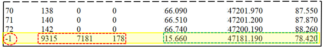
Figure 384 Insertion of remote pole in the conversion table
Only the real coordinates are used (in green in Figure 384) for remote poles, so the sequence coordinates (in the red box in Figure 384) of a remote pole can be any number (like 9315, 7181, 178 as in the example, or 0,0,0) because anyway they will be ignored.