Rototranslation
To set the Position, the Rotation, and the Scale of the object (useful if there is the necessity to emphasize one dimension). Some examples are shown in Figure 345. This is only a “graphical” rototranslation, the coordinates of the datafile do not change. It is a useful tool to visualize the project in a coordinates reference system different from the current one, in which the data were collected (in this case the axes numbers will refer to the new coordinates, but when exporting the datafile nothing has changed in it and it still is in the original coordinate system). It is also useful to make some quick evaluation to find the correct values to apply to the ERT data, to actually rototranslate them through the proper tool (see “ERT Data Rototranslation” command on ERT Data).
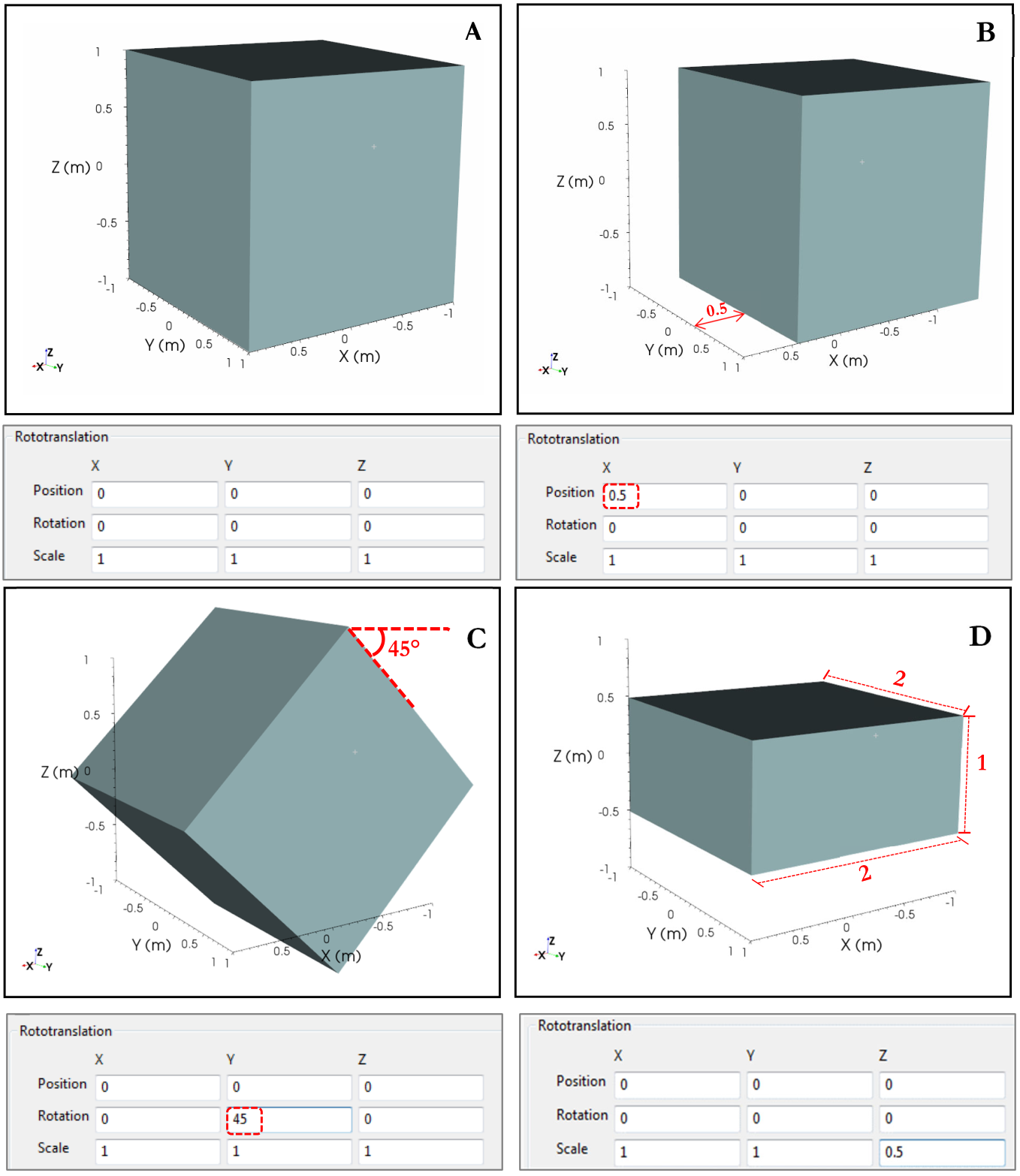
Figure 345 Some example of rototranslation. In A the cube in the original position, with the default values in the table; in B translation along X axis of 0.5; in C rotation along Y axis of 45° and in D decrease in the scale ratio of 0.5 along Z axis
Through the Position X, Y, and Z it is possible to choose the position of the object in the scene; through the Rotation X, Y, and Z it is possible to rotate the object up to 360° in the three directions, and through the Scale X, Y, and Z, it is possible to change the scale of the entire 3D scene (sometimes it may be useful to change the scale of one direction to emphasize the trend of one property, for example an alignment along one direction).
Using the button “Last Picked” it can be easily set the X,Y,Z Position from a mouse click ( see Picker setting).
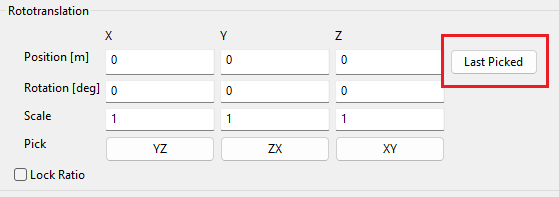
Figure 346 Last Picked point button
This table is useful when it is necessary to place the scene to a specific viewpoint and/or rotate it by a defined quantity, expressed by an exact number. Otherwise, if it is required to manually shift the scene, it is possible to use the dedicated Pick buttons.
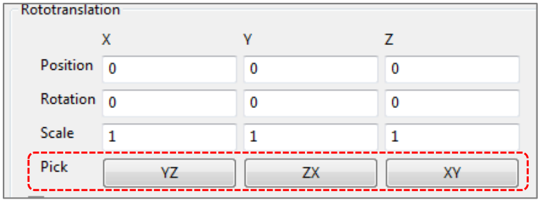
Figure 347 Pick Button in rototranslation panel
Clicking on one of these buttons, it is possible to act along the selected plane. A specific panel will appear overlaid to the object, as it is shown in Figure 348.
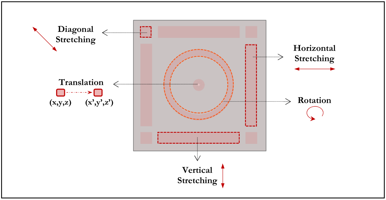
Figure 348 Manually rototranslation panel
For example, to stretch one cube along X axis drag the mouse until the desired position while holding the right mouse button. The X dimension will be changed (from 1 to 2 in this example) and the other two dimensions will remain unchanged (Figure 349).
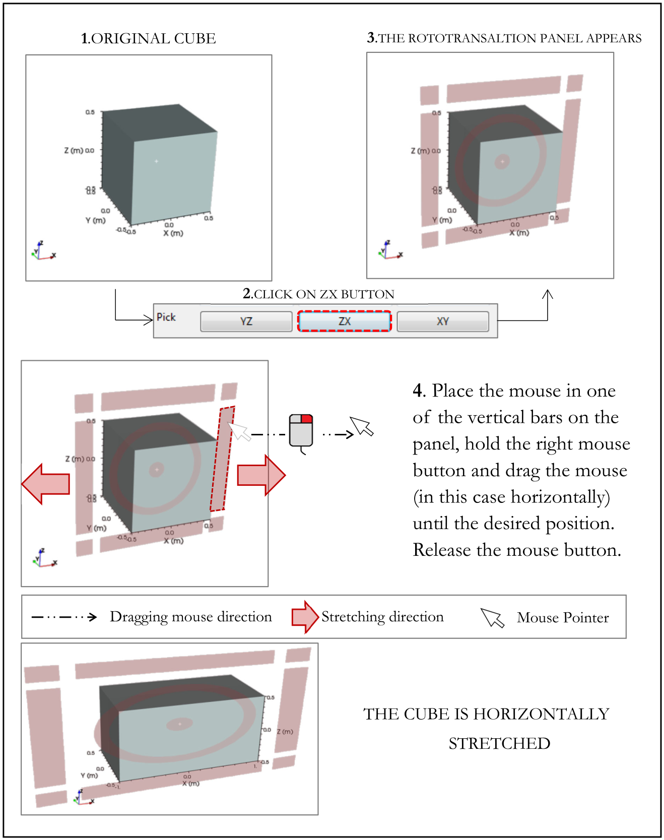
Figure 349 Example of manually stretching of a cube in one direction
If Lock Ratio is checked, dragging the mouse in one direction even the others two dimensions of the same plane will change of the same relative quantity. In the following example, the cube is deformed vertically through the mouse, but it is stretch horizontally too (Figure 350).
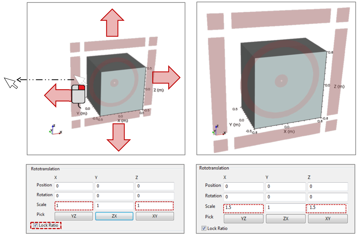
Figure 350 Example of manually stretching of a cube in two dimensions, with Lock Ration active
In the following paragraphs it will be shown how to insert various objects in the 3D scene. Each object has its position, its rotation, and its size, independently editable from other objects. Through the panel all the objects are treated as a single group. In the following example in the scene there is only one cube, but if more objects were inserted into the scene each of them will be subjected to changes made through the table. In the following example 5 spheres are placed in the scene (Figure 351).
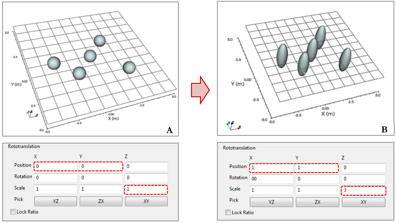
Figure 351 In A, objects in original position; in B the same objects after a change of position and scale in Scene panel
From image A to image B the position changes from 0 to 1 for the X and Y axes, and the Z axis is scaled by a factor of 3. The resulting scene is shifted and stretched along Z axis, thereby turning the spheres into 5 ovoid shape objects. But the relative position between the objects did not change.