Model Fence Section
Warning
Feature not available in the basic license; included in the “Graphics pack” add-on.
The Fence Section is similar to the Section panel, but it is used to make cuts to the mesh that are not strictly planar. The main difference in this case is that a polyline needs to be defined instead of setting the cutting plane position and orientation.
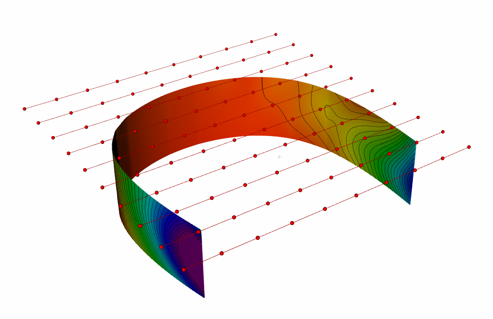
Figure 158 Fence Section
The Fence Section tabs have the panel divided into: Section and Contour.
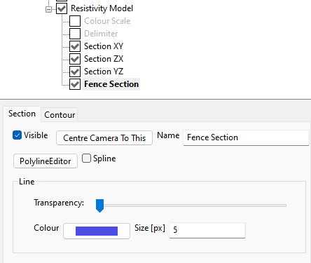
Figure 159 Fence Section properties
Section panel
The Section tab contains the following items:
Visible
Controls the visibility of the Section.
Centre Camera to This
To force the camera to view this object.
Name
To set the name of this object as desired.
Polyline Editor
Pressing this button it is opened a window to edit the polyline provided.
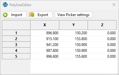
Figure 160 Polyline Editor
Import To load a text file, with numbers in a 3 column format.
Export To save a text file, with numbers in a 3 column format.
View Picker setting To open the global View Picker settings tool.
Note
To place the polyline exactly under the electrodes it can be useful to Export the electrode positions to a file, then to use the Import button in this window to load it.
With the table it is possible to edit manually the coordinate list.
To add a new row at the end of the table then right click with the mouse the 3D scene, the cursor position will be taken, according to the picker settings.
To remove one (or more) rows from the table, select them, and press the Delete key from the keyboard.
The polyline can be also edited with the mouse, interacting with the 3D scene.
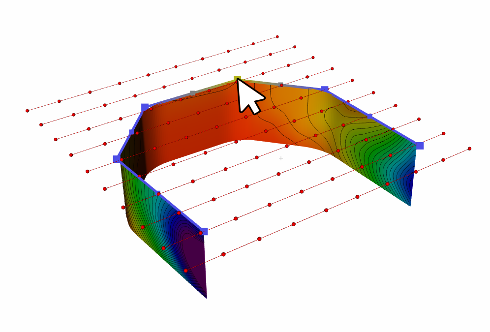
Figure 161 Polyline Editing
Edit a point: move the mouse over the desired point, it should change colour, then press the right mouse button and drag and drop it in a different position.
Delete a point: move the mouse over the desired point, it should change colour, then press the Delete key in the keyboard.
Insert a new point: can be performed like the Edit a point feature, but it is then needed to select one of the virtual points that are drawn in the middle position between adjacent real points.
Note
Note that to correctly select a point in the 3D scene the picker needs to be correctly set to let the mouse cursor be relative the correct point in the 3D space. This is also true when trying to move a point in a different position.
Spline
To smooth the polyline as a continuos curve, or to draw the polyline as a sequence of linear segments.
Line
To set how the polyline is drawn in the scene. It is possible to set the Transparency, the Colour and the Size (in pixel) of the line.
Contour Panel
For this node see Model Section.