Run Sequence Generation
By clicking with the right mouse button on the main node of the “ERT Data”, and choosing “Run Sequence Generation”, the desired data acquisition sequence can be generated.
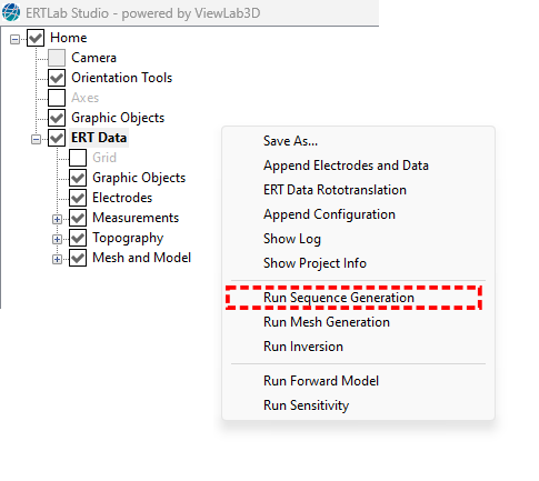
Figure 286 Run Sequence Generation
Select the array type
The first step consists in the choice of the type of array; the main configurations are available (Figure 287).
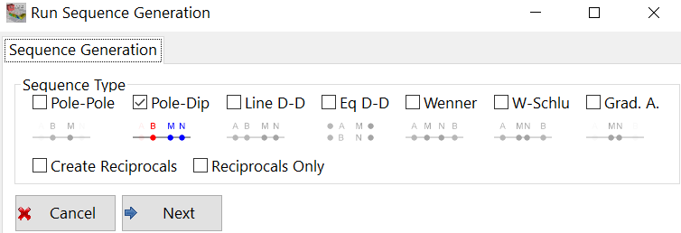
Figure 287 Sequence generation, step 1; array definition.
Under each box is a schematic indicating the geometry of the sequences, which are also described below. After having checked the desired sequence type, click a on Next button.
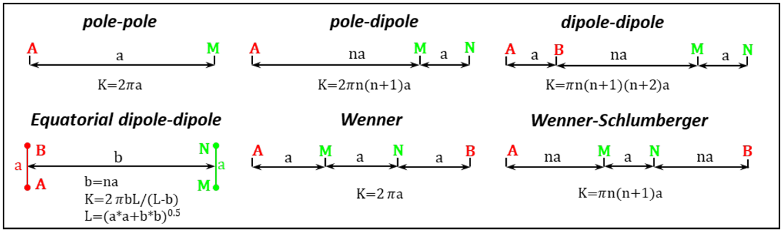
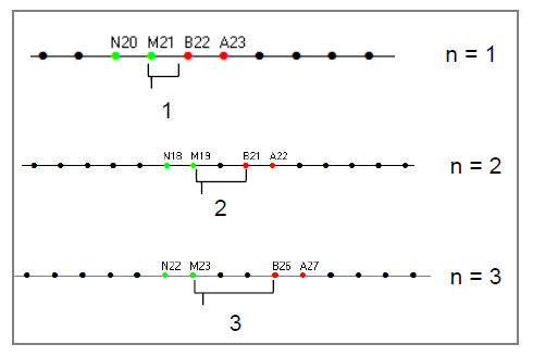
Figure 288 Main electrodes array
Choose array parameters
Once the array type has been selected, the Next button will open a window for the choice of the array parameters (Figure 289).
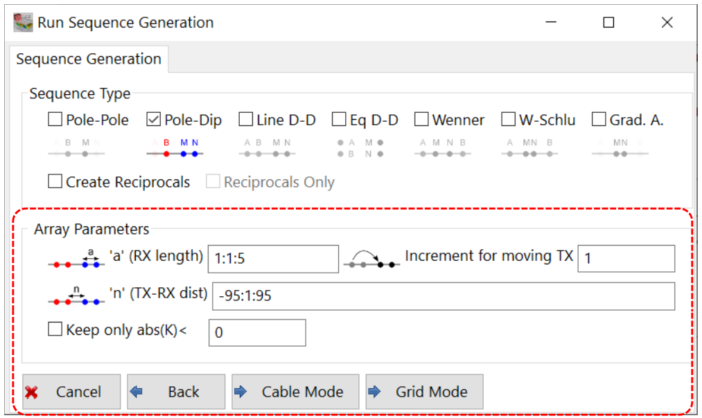
Figure 289 Sequence generation, step 2; set array parameters
Set the length of the RX-dipole (“a”), by applying the Mathematical Notation.
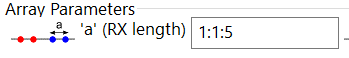
In the example, 1:1:5 the numbers are the starting value : increment value : end value, resulting in the values 1,2,3,4,5.
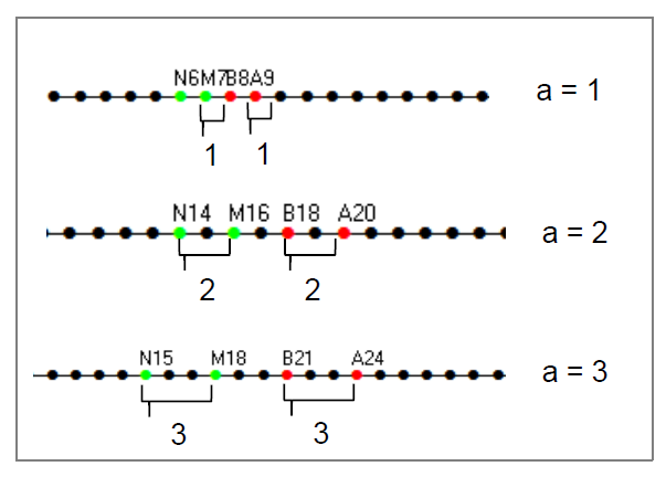
The values are reported as electrode distances, so 1 means a length equal to the length of the electrodes spacing, 2 a length equal to 2x the length of the electrodes spacing, 3 a length equal to 3x the length of the electrode spacing, etc.
Set the increment for moving TX.
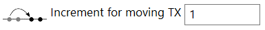
This value is expressed in units of electrodes distance as well and is set to 1 by default.
Set the distance between RX-dipole and TX-dipole (“n”), by applying the Mathematical Notation.
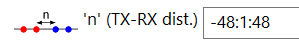
In the example, -48:1:48 are the starting value : increment value : end value, resulting in the values -48,-47,-46,-45, ….,0,1,2,3,……47,48.
The values are also reported in dipole distances (take-out distance), so 1 means a length equal to the length of the TX-RX dipole, 2 a length equal to 2x the length of the TX-RX dipole, etc.
Constrain the generation of quadrupole to geometric factor. If the options is selected, the quadrupoles are generated only if the geometric factor K is less than the entered value. This parameter is used to limit the number of measures and avoid the generation of quadrupole with low signal/noise ratio (that is often related to a quadrupole with high “n” value having a long distance between TX and RX). The geometric factor threshold can be for example set to 1500 times the electrode spacing to remove many poor quadrupoles.

Select Insertion Mode
There are two methods for the generation of sequences:
Cable Mode
Grid Mode
To switch to one insertion mode to the other, click on the “Back” button (in yellow in Figure 290) and choose the desired tool.
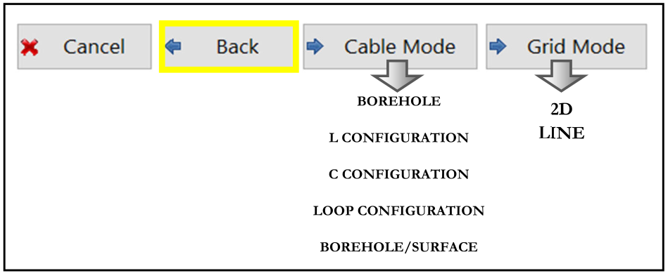
Figure 290 Choice of sequence mode generation
Cable Mode
It generates the sequences for cross-cable mode, having transmitters and receivers on different cables.
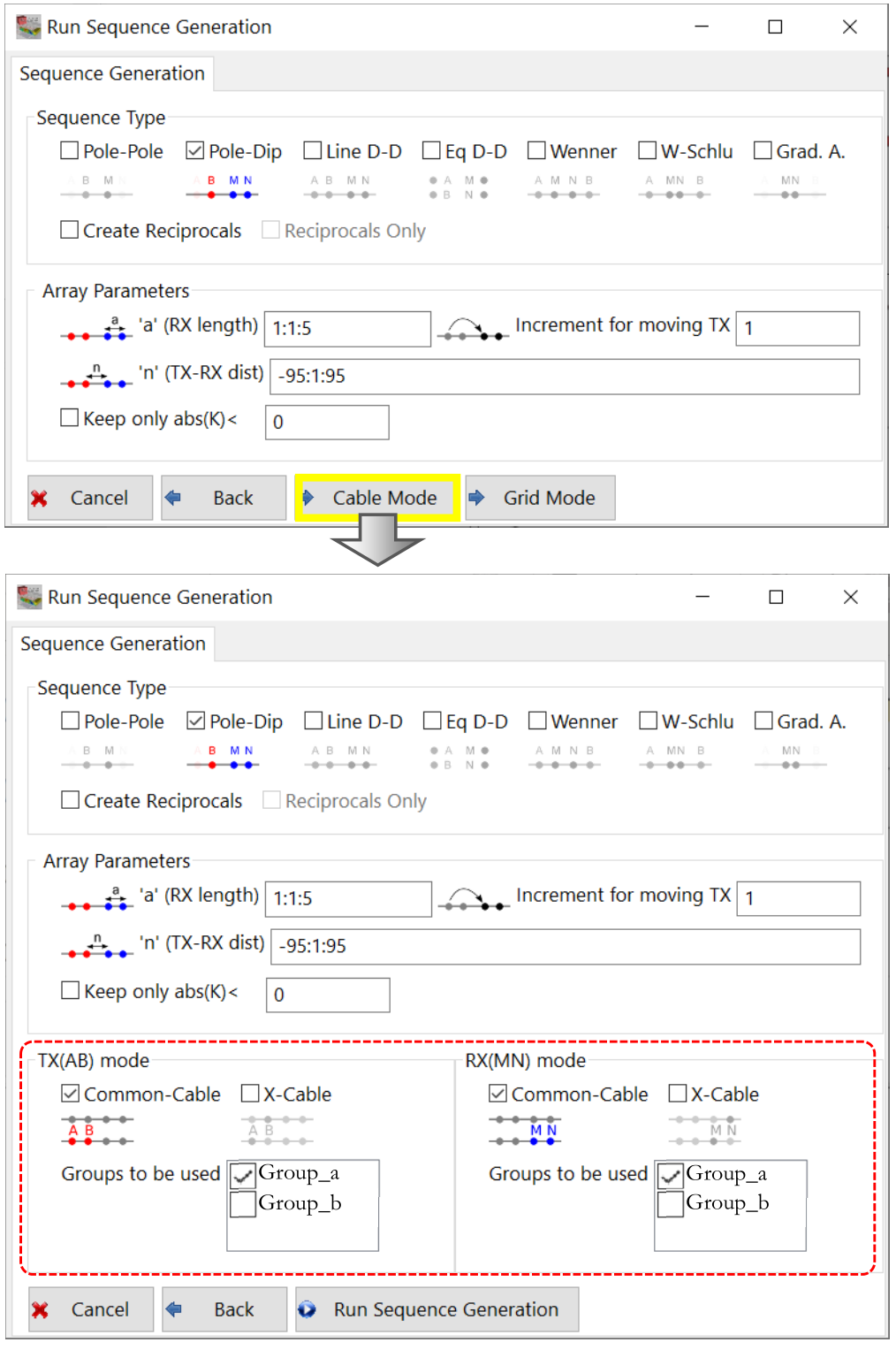
Figure 291 Cable-mode insertion panel
It lets the user manage borehole acquisition, surface acquisition with L or C configuration and borehole-surface acquisitions. The panel is separated in TX cable tools on the left and RX cable tools on the right. In both cases it is possible to choose to put the TX or RX in the same cable (Common-Cable selection box) or in separated cable (X-Cable selection box). Figure 292 shows an example for a TX dipole. The RX dipole can be configured like this as well.
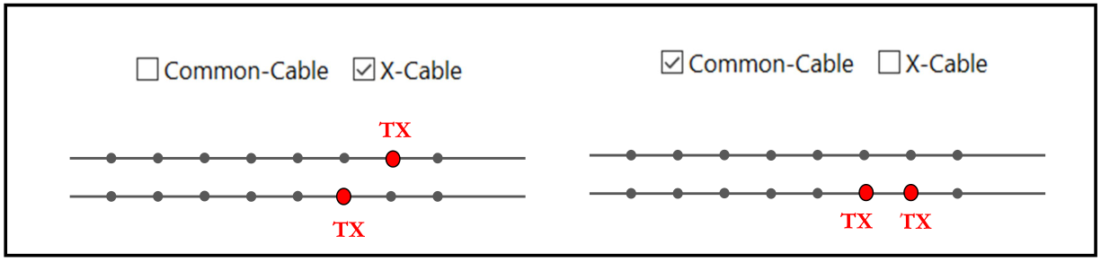
Figure 292 Example of Common Cable/Cross Cable TX
The Group on which to put the RX and the TX is selectable at the bottom of the window checking the appropriate box (in Figure 293 two cable are load in the project, Group_a cable and Group_b.)
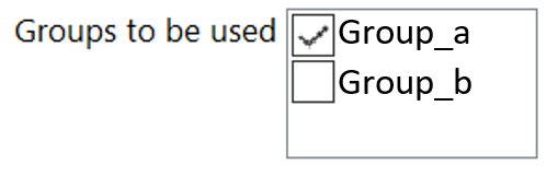
Figure 293 Groups where to put TR/TX
Clicking on Run Sequence Generation button generates the electrode sequence specified and a confirmation message will appear when the generation is completed (Figure 294).
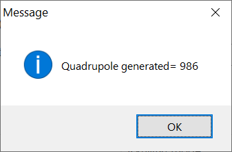
Figure 294 Quadrupole generated information message
Starting again from the beginning of the sequence generation procedure and creating a new sequence. A new message will appear, to choose adding the new sequence to the previous, or deleting the older and keep only the last sequence generated. In either case a new message will indicate the resulting numbers of new quadrupole generated.
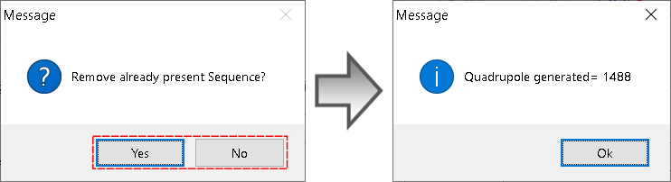
Figure 295 Panel to choose if remove or not the previous sequence
Grid Mode
It generates the sequences for 2D surface profiles or 3D grids.
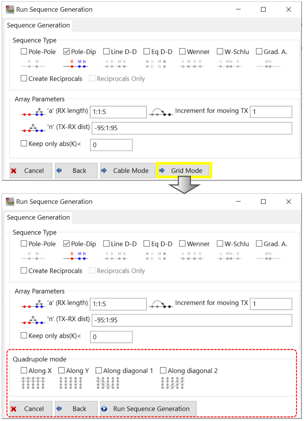
Figure 296 Gird-mode insert panel
Through this panel it is possible to choose the quadrupole direction, which can be along the main X and Y Axes and in diagonal. As seen in Figure 297, each button helps to make the wanted choice.
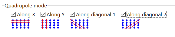
Figure 297 Choice of quadrupole acquisition direction